- Contact 0870 350 7767
- |
- Advertise

Heat Sensors Case Study
 News and PR from Carrs Welding Technologies Ltd - Published 29 November 2019
Carrs have been working for the aerospace industry for over 6 years now. We have been awarded the AS9100 quality standard for 4 years running, proving Carrs consistency and standard of work.
News and PR from Carrs Welding Technologies Ltd - Published 29 November 2019
Carrs have been working for the aerospace industry for over 6 years now. We have been awarded the AS9100 quality standard for 4 years running, proving Carrs consistency and standard of work.The Overview
In the aerospace industry, sensors hold a very important role as it is crucial for the safety of all staff/customers to assess the thermal state of an engine during testing and flight conditions. For this reason, Carrs Welding Technologies Ltd. were approached to weld a heat sensor consisting of several tube arrays into a housing on a GE engine.
The Context and Challenge
Project background and description
As mentioned, the project consisted in the welding of several arrays of 2mm diameter tubes into a housing on a GE engine. The chosen material was the Nimonic alloy C263 due to its combination of good aged strength and excellent fabrication characteristics.
The problem
The shape and tight spacing between arrays of tubes meant that the application was unable to be rotated. At the same time, the small tube diameter and thin wall thickness meant that the volume of material available to disperse the heat from the welding operation was severely reduced. This posed two problems:
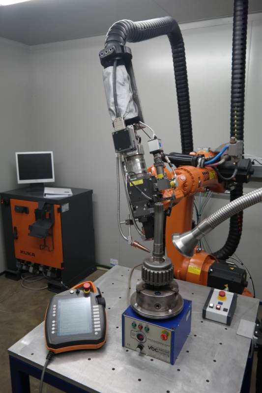
The first issue was the fact that a 6 Axis Robot arrangement was not precise enough to follow a circle with such small diameter accurately due to evident process intolerances, i.e. the robot trying to create a circular shape with linear paths.
The second issue was directly linked to the customerÂs request to weld the outside diameter without melting the internal diameter whilst achieving a full weld depth to the base plate which meant two things, the need for a fast weld (as not to overheat the material) and the tight weld depth/width tolerance (i.e. usually the weld depth varies during the welding operation due to a temperature build-up on the base metal as the weld progresses).
Project goals and objectives
The project goal was to weld arrays of tubes all around without melting the internal diameter whilst achieving a full weld depth onto the base plate.
The process and insight
Continuous wave laser welding was chosen for this application due to several key aspects; the ability to perform faster welds (when compared to Pulsed Laser Welding) allowing for the decrease of the heat input; and the ability to enter the keyhole mode which would allow for weld profiles with lower weld width to weld depth ratios, i.e. deeper welds without melting the walls of the tubes.
The solution
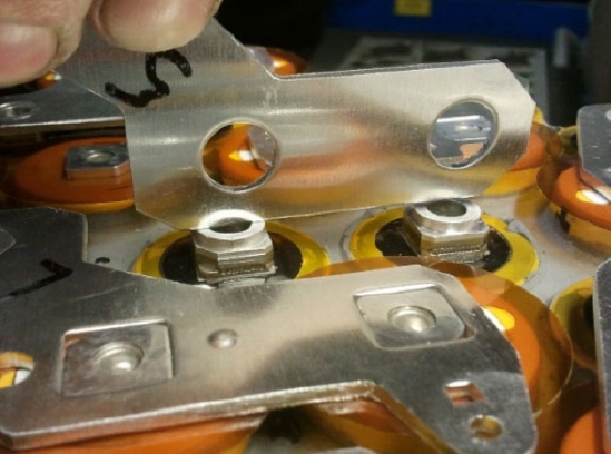
The solution to the tight spacing between tubes and inability to be rotated was the design of an offset cam arrangement to manipulate the tubes and achieve the continuous weld under a stationary laser head. The next step was to find the right weld profile, by adjusting the laser interaction time and laser power.
The results
The actual parts could not be shown, but the test piece on figure 1 shows the spacing between the arrays.


 The solution to the tight spacing between tubes and inability to be rotated was the design of an offset cam

Other announcements from Carrs Welding Technologies Ltd
-
Battery Welding Modules Case Study
Carrs weld numerous parts for the car industry from clutch plates to collapsible steering column assemblies.
29 Nov 2019
-
Tooling Repairs
Steels, especially hard tool steels can be welded conventionally but the heat and the stress introduced with Tig welding make it almost impossible to remove all witness to the repair.
29 Nov 2019
-
TWI Industrial Membership
Carrs Welding Technologies Ltd is pleased to announce that it has recently become a TWI Industrial Member.
23 Jan 2017
-
Laser welding goes mobile for on-site repairs
Carrs can now bring their welding expertise to your door.
01 Nov 2016
-
Carrs go large with 6kWatt laser welder.
Carrs Welding Tech have now commissioned their latest Trumpf 6 Kwatts welding laser. The new laser provides important back up for the 4Kwatts disk already installed at Carrs
21 Jul 2016
-
Mobile Services with on-site welding
Carrs are now bringing their welding expertise to your door.
08 Apr 2016
-
-
Carrs celebrate 15 year collaboration
Carrs celebrate 15 year collaboration with Rofin-Baasel
01 Oct 2013